A gentle introduction to Tao.OpenGl using SimpleOpenGlControl.
Preface
Hello. I'm Nikos Kouremenos, and what follows is a way to play with Tao.OpenGL in Borland's C# Builder (which you can get freely by Borland's main site).
I first wanted to make this tutorial about SharpDevelop and Tao.
But then I realized that SharpDevelop couldn't see the components in the dll needed.
So until I find a solution or SharpDevelop gets even better, I used C# Builder Personal Edition, which is not free software, but at least it is free (beer).
I would like to thank
Randy Ridge
for Tao and Jordan Weber-Flink because I borrowed some text from his tutorial for VB.net
Note: In the shots and in the source I provide, the project is called SimpleInto (I accidentally remove the r). That's not something to worry about. :)
UPDATE:You can also use this document with Visual Studio PE C# which is also free. Piotr Karpała was kind enough to send me his source files, which you can find at the bottom next to Borland ones.
What is SimpleOpenGlControl?
SimpleOpenGlControl is just that, a simple Windows Forms-based OpenGL control. Its purpose is to get your OpenGL application quickly running with Windows Forms. It abstracts some of the complexities involved with setting up an OpenGL context on Windows. It allows you, the developer, to quickly write a Windows Forms-based OpenGL applications in a simple way. I highly recommend SimpleOpenGlControl for those of you new to OpenGL or those of you who want to quickly write a Windows Forms-based OpenGL application. If you later find that SimpleOpenGlControl does not fit your needs, it's usually relatively easy to switch over to using other methods to handle the functionality that SimpleOpenGlControl provides.
Let's get started!
Let's make sure you have the latest, official Tao Framework. Go to the framework download page and download and install the latest Tao Framework Setup file. This file installs the libraries into the systemroot (e.g. C:\WINNT\System32) as well as to the Global Assembly Cache, which helps speed up start time. With these two things taken care of, we can begin coding!
Create a solution and project.
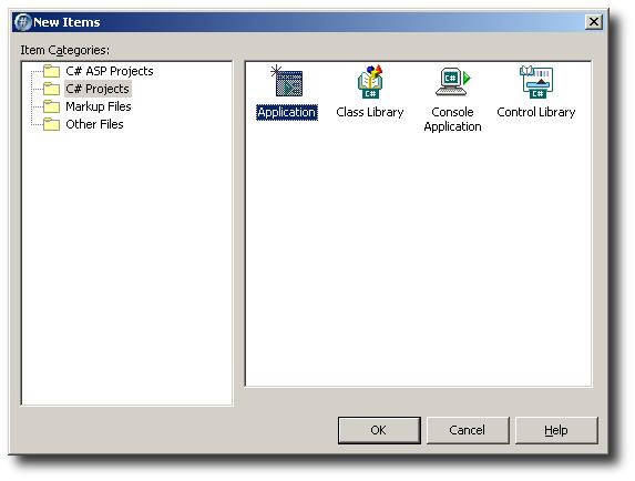
We'll start by opening C# Builder and creating a new Windows application project:
C# Builder will generate some code for us:
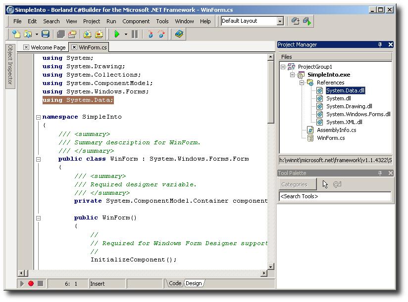
Note the references. We have no need for System.Data and System.XML.
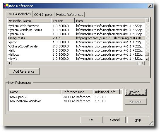
I'll right click on them and choose Remove, leaving us with only System, System.Drawing, and System.Windows.Forms. I'll also remove the "using System.Data;" from Form1.cs to avoid a compilation error. We do however need to reference Tao.OpenGl and Tao.Platform.Windows. We can either go to Project/Add Reference or right click on References in the Solution Explorer and choose Add Reference. On the Add Reference dialog we'll choose Browse... and we'll navigate to where we have Tao.OpenGl.dll and Tao.Platform.Windows.dll (most likely in your systemroot, e.g. C:\WINNT\System32). We double click on Tao.OpenGl.dll and Tao.Platform.Windows.dll and they will be added:
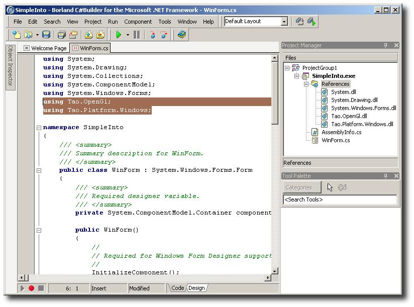
Now we can begin using Tao.OpenGl and Tao.Platform.Windows. We'll start by doing just that, by adding a "using Tao.OpenGl;" and "using Tao.Platform.Windows;" statements to import the namespaces. You should notice that you have Intellisense support and note the references have been added as well (I also removed the generated comments and changed formatting for brevity):
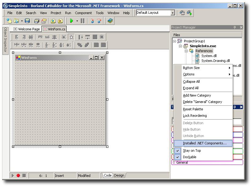
You should probably take this time to ensure that everything compiles and runs, even though it won't do too much, but you will get a generic, blank window :) At this point we're ready to add the SimpleOpenGlControl. We'll go to our Toolbox, right click and choose Add/Remove Items:
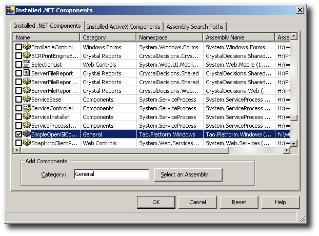
We will choose Browse... and again navigate to the location of Tao.Platform.Windows.dll (most likely in your systemroot, e.g. C:\WINNT\System32). We double click on Tao.Platform.Windows.dll and are returned to the Customize Toolbox dialog, with SimpleOpenGlControl checked:
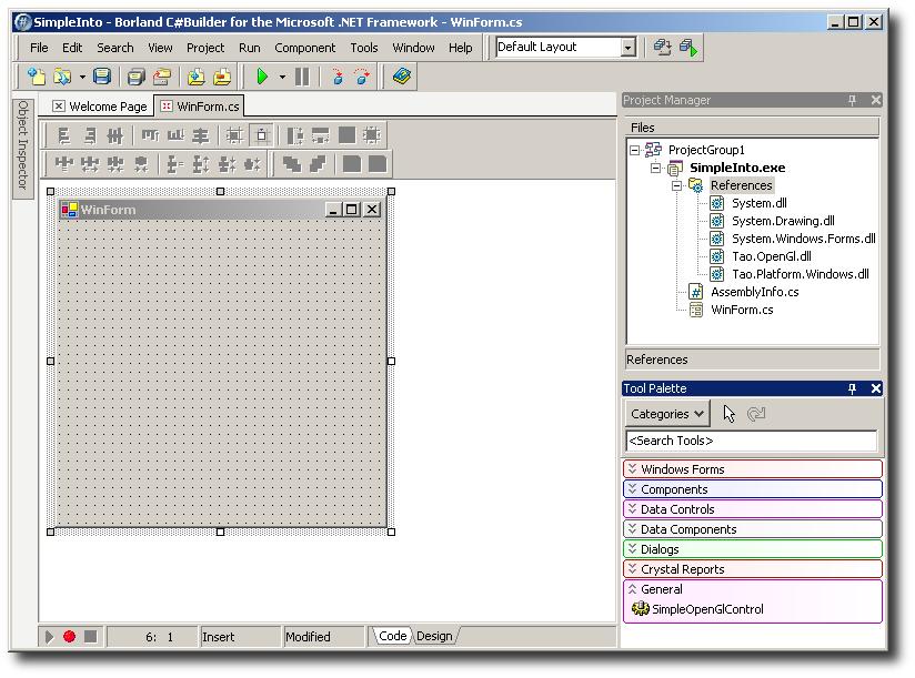
We click OK, return to design mode, and expand the Toolbox. You should notice "SimpleOpenGlControl" listed under the Windows Forms panel:
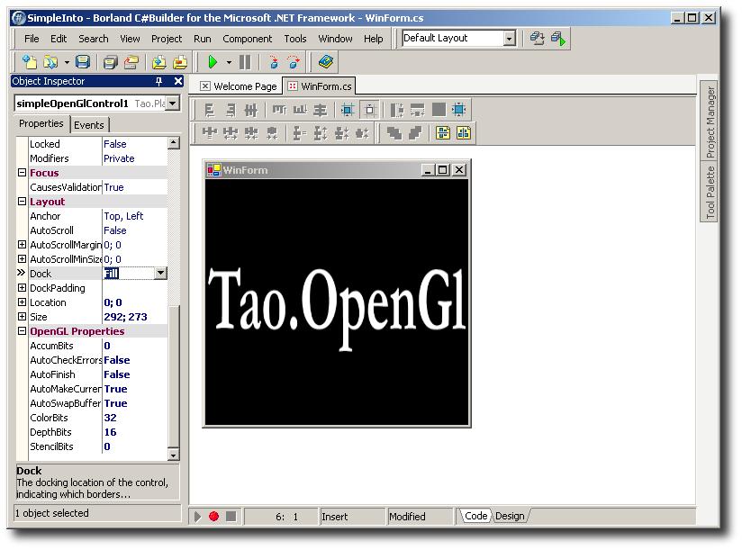
We then drag the "SimpleOpenGlControl" onto our form. I then go to Properties/Dock and choose DockStyle to be Fill:
I then might like to changes some other properties of the control to suit my needs, the SimpleOpenGlControl has a property group called OpenGL Properties which control various context creation values. However, I am going to stick with the defaults. If you try to run the application at this point you will receive an error stating that "No device or rendering context is available!". Egads! This is because we haven't actually initialized the OpenGL context. We'll do so by adding a call to the InitializeContexts method somewhere after the SimpleOpenGlControl is instantiated, we'll also be a good citizen and make sure to call DestroyContexts in the Dispose method:
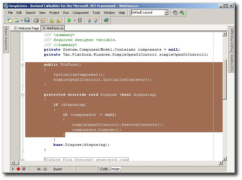
InitializeContexts and DestroyContexts do exactly what they say, initialize/create and destroy the OpenGL context. These are manual calls to allow you to change various properties on the control before it's created and to ensure that the context is destroyed when you're done with the control. Don't forget them! At this point you may run the program and it should present you a window with a black background. This window has an OpenGL context, congratulations, you now have an OpenGL Windows Forms app up and running. It's fairly boring, so let's add some OpenGL initialization:
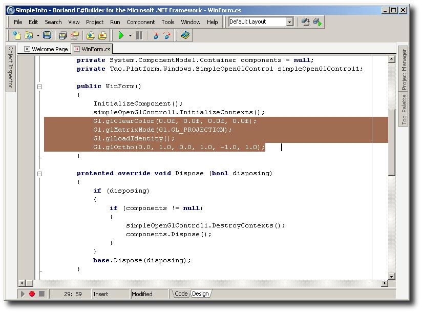
I think I'll take a moment here to explain what we're doing for OpenGl initiates. glClearColor is a function which informs the OpenGl framework we are using what color to use when clearing the screen. The four values are floats representing Red, Green, Blue, and Alpha. Ignoring the alpha channel, you can combine RGB values to make a whole lot of colors. Black being the absence of light, an RGB value of 0 0 0 is black. White light is the unity of all colors in the spectrum, so an RGB value of 1 1 1 makes the clear color white. If you like, you can use 0 0 1 to make a very intense blue or .5 .5 .5 to make gray.
glMatrixMode tells OpenGl which Matrix we are using - any matrix operations performed by OpenGl via calls will be performed on the Projection Stack. There are four matrix stacks in OpenGl - the Modelview stack, the Projection stack, the Textures stack and the Color stack. The initial mode for OpenGl is the modelview mode, but we're only interested in the projection stack. If you are unfamiliar with computer graphics, suffice it to say that matrices are very convenient for representing 3D space and performing operations on them is an easy way to alter that 3D space. For example, if you did a matrix rotation operation when OpenGl was in modelview mode, all the objects / geometry on the modelview stack could be made to rotate. We are only interested in altering the way the Projection stack works - it is the stack that maps the 3D space onto your 2D window, kind of like an old-fashioned reel projector (hence projection stack).
Currently, our projection matrix stack is empty. glLoadIdentity loads what is called the "Identity Matrix" onto the projection stack (because we are in the projection matrix mode due to our previous call to glMatrixMode). The Identity Matrix is a matrix where all values are 0 except on the diagonal - kind of like this:
1 0 0 0
0 1 0 0
0 0 1 0
0 0 0 1
Doing matrix operations like multiplication with the Identity Matrix as the operand results in the same matrix. It's kind of like 1 in ordinary arithmetic. Any number you multiply by 1 results in itself, eg 27*1 = 27. The Identity Matrix works the same way in linear algebra (the math of matrices) and so it's a very useful thing to have.
Then we have glOrtho. This one's a doozy :)
glOrtho multiplies the current matrix (remember, we have the identity matrix sitting on the projection stack) by an orthographic matrix. Since the result of matrix multiplication by or on the Identity Matrix results in the multiplicand, so whatever orthographic matrix we use as the arguement to the glOrtho function will now be sitting on the stack. So why even bother with the Identity Matrix in the first place? Why not just use glPushMatrix to push our orthographic matrix right onto the projection stack? Well, you could do that if you wanted. But it is considered better form to initialize all stacks with an Identity matrix and work from there.
"Ok," you mutter, "but what the heck is an orthowhatsit?"
An orthographic matrix results in an orthographic projection, which is like a view without depth. In an orthographic projection, everything in 3D space is mapped straight forward onto the 2D space. Imagine an Orange sitting on a table. If you looked straight down at it through a square piece of glass, you have a sense of perspective, of depth. Now imagine that you squashed the glass down on top of the orange until it was perfectly flat. No more perspective, just an orange circle with some texture to it. That's kind of what an orthographic projection is like. We use it to teach beginners about projection because it is easier to understand and use than glFrustrum, which produces a perspective projection.
We need to tell OpenGl how big our piece of glass (2D window) is, and where it is in relation to our orange (geometry in computer memory 3D space). So first we tell it where the left and right clipping planes are. A left clipping plane is like a big sheet of paper standing on its edge on the left side of the table. It extends all the way up to the sky, way down into the ground, and as far ahead of you and behind you as you can imagine. You cannot see anything to the left of it whatsoever. The right clipping plane is the same thing but on the right. So now we can see our table, our fruit, and the horizon in front and behind us, but nothing to the left and right of the clipping planes.
Randy has chosen to use the value 0.0 for the left clipping plane and 1.0 for the right clipping plane. He's setting up a coordinate system - any geometry which resided between 0.0 left and 1.0 right can be seen through our piece of glass - but a point at -0.1 cannot be seen and neither can a point at 1.1.
Next we set up our bottom and top clipping planes. Top and bottom are very misleading terms - we are looking straight down at our table so by "top" we mean something hanging straight down from the top of our heads and by "bottom" we mean something hanging from our chins. Again Randy uses 0.0 and 1.0. So now if we are directly above the table looking down, we can see anything inside a square that is 1.0 units width by 1.0 units length. It doesn't matter what the unit is - it could be 1.0 inches (very small orange) or 1.0 miles (very big orange). For our purposes it's closer to 1.0 feet but it honestly doesn't matter.
So now we have this lovely square that we are looking through, but how close are we to the orange? Are we looking at it from directly above it or from the top of a ladder looking down? In the case of an orthographic projection, it doesn't matter - no matter how far we are from the orange, all of its color comes straigh up at us. We have no perspective. We could be 10000 feet in the air and it would look the same. Of course in a perspective projection, the farther away we get the smaller the orange appears, and the closer we get, the bigger it appears. But we're not, so why do we need to know?
The answer is that our orthographic projection matrix needs to know where to draw the z-clipping planes. Z is the axis that goes from our eyeball to the fruit. We need to tell OpenGl that it must draw everything from our eye to a little bit past the orange. Why? Well, in the future as we learn more complex OpenGl principles, that will become more obvious. But basically OpenGl doesn't want to draw infinity, so we tell it to only worry about the geometry between our clipping planes and ignore everything else - 3D space is infinite! Randy chooses -1.0 for the backplane and 1.0 for the foreplane. This means we now have a rectangle of 2 cubic units - 1.0 units in the air behind our piece of glass and 1.0 units past it. Our orange is somewhere within the 1 cubic unit in front of us, and OpenGl knows to paint it onto our glass by shooting all the color information straight up without perspective. Hooray!
Finally, we'll clear the window and draw a triangle. We'll do so by adding an event handler to the SimpleOpenGlControl's Paint event:
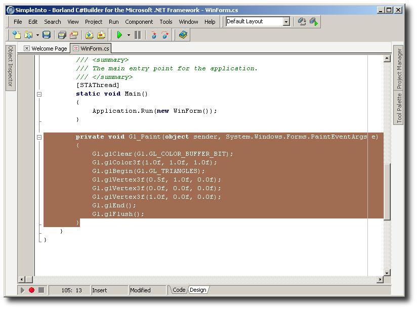
What's going on here? Good question. Ok, throw the orange out of the window - that metaphor's time is up. What we're doing is drawing a very simple triangle.
First we call glClear. This function (unsurprisingly) clears our some of OpenGl's buffers. It knows which buffers to clear by the arguments you pass to it. When you pass in the GL_COLOR_BUFFER_BIT, it tells the function to clear out the color buffer. The reason it is a bit is because bits can be OR'ed together so that the funtion only receives one argument but can still find out what it is supposed to be doing. So, if you had a bunch of crap in the Z-buffer, you could call glClearColor(Gl.GL_COLOR_BUFFER_BIT | Gl.GL_DEPTH_BUFFER_BIT). This would OR the two bits together and produce one arguement which glClearColor can use to decide it should clear both the color and depth(z) buffers.
Next we use glColor3f. There are lots of ways to tell OpenGl what color you want to use - this one uses three floats to represent Red Green and Blue. We pass in 1.0 1.0 1.0, which tells OpenGl we want it to draw with the color white.
Next we use glBegin and another bit, GL_TRIANGLES, to tell OpenGl we are ready to begin rendering (drawing) actual geometry (in this case a flat triangle). Next we pass it the vertices of the triangle. Tip: in OpenGl we draw convex polygons by passing in their vertices in counter-clockwise order. If you pass in the vertices in clockwise order, OpenGl thinks it is looking at the "back" of the polygon, and if you turn on backface culling to improve performance, it will not render the triangle at all. (If that's confusing, don't worry about it). Remember, our coordinate system maps on to the screen with the bottom left corner being 0, 0, 0 (XYZ); the top left being 0,1,0; the top right corner is 1, 1, 0; and the bottom right corner is 1, 0, 0. Because we are using an orthographic projection and a flat piece of geometry, we leave the z-coordiates alone at 0 and paint it directly onto our window.
The first vertex is .5, 1, 0: draw a vertex at the center of the screen going from left to right (on the 2D projected space), and at the top (1.0) from top to bottom (again on the 2D projected space). The next corner is at the bottom left and the final corner is at the bottom right. We use glEnd to tell OpenGl that we are done drawing and glFlush to tell OpenGl "Hey! Don't wait, go paint this right now!"
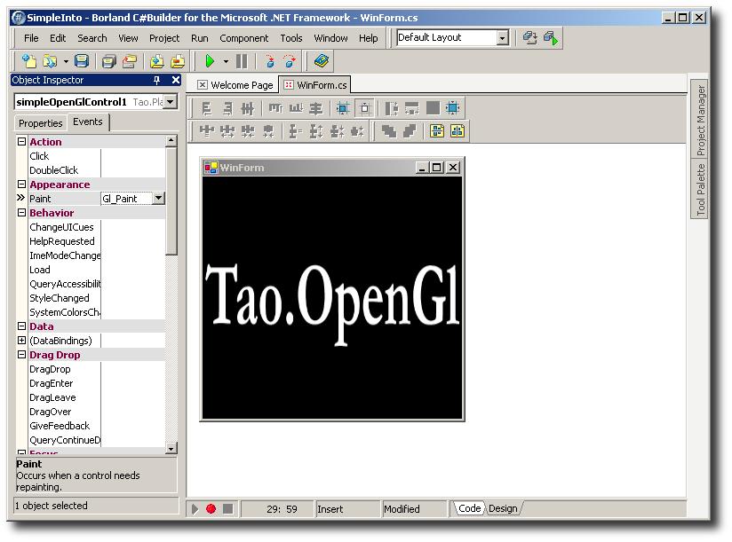
At this point we should have a window that looks like this:
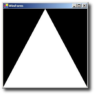
Congratulations. Your first OpenGL application using Tao.OpenGL's SimpleOpenGlControl.
Get the source and binaries for this example Borland C# Builder, Visual Studio PE C#
Get this page for offline reading (images included)
